X-ray Fluorescence
Learn More About XRF and Using Rigaku EDXRF Technology
What is EDXRF Spectroscopy?
EDXRF (energy dispersive X-ray fluorescence) is a non-destructive analytical technique that provides quick qualitative and quantitative elemental analysis of a wide range of matrices, from low ppm to high weight percent concentrations. It is a common type of X-ray fluorescence (XRF) because it offers a fast, reliable, and economical solution for determining elemental composition. EDXRF addresses many analytical needs — from testing and screening oils and liquids to analyzing solids, metals, polymers, powders, pastes, coatings, and thin films — while still suiting budgets and occupying only a small amount of space in the lab or testing facility.
EDXRF instruments are easy to use and inexpensive compared to other technologies. Sample preparation is minimal, and since EDXRF is a non-destructive technique, samples are preserved and not destroyed. It is an excellent option for many industries and applications.
- EDXRF is a non-destructive analytical technique that provides quick, multi-element analysis in a wide range of matrices.
- EDXRF can measure sodium through uranium, depending on the application.
- EDXRF systems are easy to use, require little to no sample prep, and offer a low cost of ownership.
- EDXRF applications range from industrial and in-plant quality assurance to research and development and many others.
- EDXRF measures the X-ray energies of the detected elements.
How does EDXRF work?
EDXRF is a spectroscopic technique that relies on X-ray excitation of a sample. X-rays are part of the electromagnetic spectrum, similar to visible and UV light, but X-rays have higher energies and can pass through sample materials. In EDXRF, source X-rays penetrate a material, causing it to fluoresce unique X-rays of energies characteristic to the elements present in the sample.
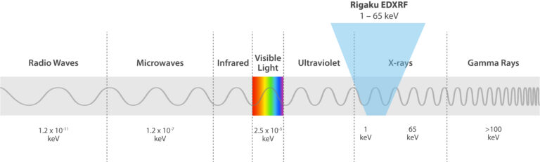
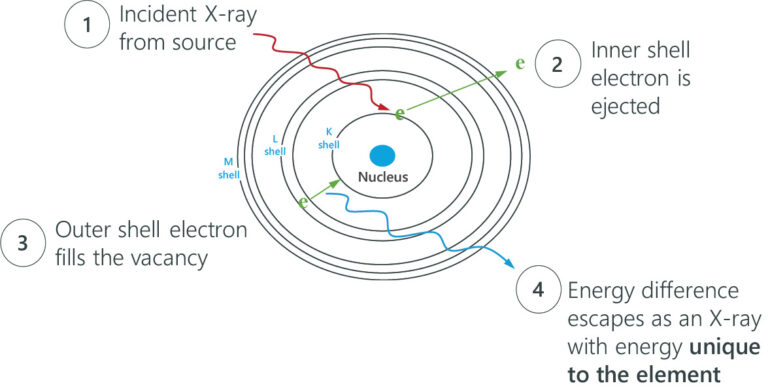
Rigaku EDXRF spectrometers use X-rays in the 1 – 65 keV energy range and employ the photoelectric effect to determine elemental composition. This effect is when incident X-rays irradiate atoms in a sample, and the sample material excites and fluoresces energy in the form of X-rays. When this phenomenon happens, electrons eject from inner atomic orbitals, causing an electron from a higher-energy orbital to transfer and fill the vacancy in the lower-energy orbital. The excess energy is emitted as an X-ray, and the spectrometer counts and measures the energies of these X-rays emitted from the sample. These energy differences between each shell are always the same for a particular element, so the spectrometer identifies and quantifies which elements are in the sample.
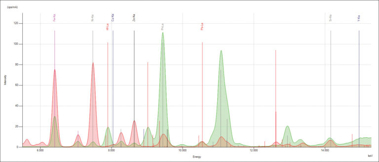
When electrons fall from the outer to the inner atomic shells, these X-ray transition lines produce peaks in a spectrum. Each transition line creates a peak at a specific energy in the spectrum of the element.

The Evolution of EDXRF Technology
Over the years, XRF is increasingly the analytical tool of choice for measuring the concentration of atomic elements in a wide range of materials. Due to ongoing evolutionary developments and revolutionary breakthroughs in X-ray sources, optics, and detector technologies, it has become a more powerful quantitative technique.
From the introduction of commercial wavelength dispersive X-ray fluorescence (WDXRF) spectrometers in the mid-1950s to the development of energy dispersive X-ray fluorescence (EDXRF) instruments in the early 1970s, the increasing availability of affordable computational power was critical to the desirability and acceptance of the XRF technique. With the widespread availability and use of the personal computer (PC) as the industry standard platform in the mid-1980s, XRF techniques became more accessible, and they offered a lower cost-of-ownership alternative to earlier atomic spectroscopy analytical techniques.
Today, with more recent developments in EDXRF, EDXRF spectrometers bring a new level of analytical sensitivity and ease of use to XRF technology.
Learn More About Rigaku EDXRF
Many industries and organizations use Rigaku EDXRF instruments to solve their analytical needs. Applications range from industrial and in-plant quality assurance to research and development, agriculture, mining, and more. Applied Rigaku Technologies provides users with advanced, high-quality EDXRF analyzers and offers customer-focused solutions and support backed by Rigaku innovation and years of EDXRF experience.
Our Product Portfolio
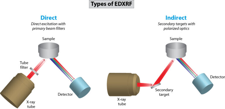
Our benchtop EDXRF systems are multi-element analyzers that deliver rapid qualitative and quantitative elemental analyses and address the needs of many applications. They provide non-destructive analyses of sodium to uranium from low ppm levels to high weight percent concentrations in almost any matrix. Our benchtop portfolio includes the compact NEX QC Series for routine quality control needs, the high-performance NEX DE Series for bulk and small spot analysis applications, and the advanced NEX CG II Series indirect excitation analyzers for trace elements and variable-base matrices, ideal for complex applications and research.
For real-time process control needs, we offer in-line and on-line solutions for continuously measuring and monitoring industrial processes so technicians can keep quality and costs in check. Process control systems include the NEX XT total sulfur analyzer for crude oil, marine fuel, and blending operations, the NEX OL multi-element process analyzer for liquid streams, and the NEX LS scanning multi-element coating analyzer for web and coil applications.
We Are Experts in EDXRF Technology
Applied Rigaku Technologies, a division of Rigaku, engineers, manufactures, and distributes Rigaku EDXRF products worldwide. Located in Cedar Park, Texas, USA, our company specializes in benchtop and on-line spectrometers for the non-destructive elemental analysis of solids, liquids, powders, coatings, and thin films. Learn more about Applied Rigaku Technologies.